Introduction
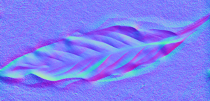
Photometric Stereo is a method for capturing the shape of a surface using the shading differences from lighting conditions, which provides pixel-resolution surface normal maps, meaning the only limit to spatial resolution is that of the camera itself. It has the added advantage that it separates the aesthetic texture (albedo) of the surface from the underlying surface shape – it can essentially see through camouflage!
How does it work?
In simple terms, we take several pictures (typically grey-scale) of the same static object, from the same static camera, but we change the lighting direction for each image. By looking at how each pixel’s intensity changes under the different conditions, we can estimate how that surface is oriented, relative to the lights.
Some Key Assumptions
Before we start, there are some import assumptions about the surface we’re imaging and the lights.
Firstly, we assume that the surface exhibits Lambertian reflectance, i.e. the amount of light reflected from a surface is directly proportional to the angle between the light direction and the surface normal.
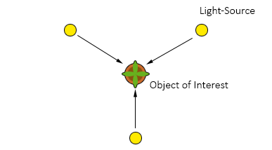
The other key assumption is that the lights are point sources – they come from infinitely far away, so the rays are parallel and you don’t get differences in illumination across the image.
Realistically, rarely are both these assumptions held completely, and so there are certain steps we can take to improve estimation accuracy, but I’ll take about that in a later post.
Solving the Surface at a Given Pixel
The relationship between the light direction, 

![I (x,y) = \rho(x,y) L . N (x,y) = \rho(x,y) \left[ \begin{array}{c} L_x\\ L_y\\ L_z \end{array}\right]^\top \left[ \begin{array}{c} N_x (x,y) \\ N_y (x,y) \\ N_z (x,y) \end{array}\right]](http://s0.wp.com/latex.php?latex=I+%28x%2Cy%29++%3D+%5Crho%28x%2Cy%29+L+.+N+%28x%2Cy%29+%3D+%5Crho%28x%2Cy%29+%5Cleft%5B+%5Cbegin%7Barray%7D%7Bc%7D+L_x%5C%5C+L_y%5C%5C+L_z+%5Cend%7Barray%7D%5Cright%5D%5E%5Ctop+%5Cleft%5B+%5Cbegin%7Barray%7D%7Bc%7D+N_x+%28x%2Cy%29+%5C%5C+N_y+%28x%2Cy%29+%5C%5C+N_z+%28x%2Cy%29++%5Cend%7Barray%7D%5Cright%5D+&bg=ffffff&fg=000&s=0&c=20201002)
We assume that 


By re-arranging the above equation, we can isolate the lighting directions from the surface normals and albedo, such that we first solve for 


Now we simply solve G for a given pixel using the using normal equations as follows:

We can work out 


Solving for all Pixels
We could loop over every pixel and work calculate that value, but it’s not overly efficient. Instead, we can take advantage of a technique known as “broadcasting” (in Python), and also supported by Matlab. We get all three greyscale images and flatten them into column vectors, then vertically stack them into a new matrix, which we’ll call 


Now we can solve similarly to the above for all pixels at simultaneously, just as we do above:
Once we’ve calculated G, we can normalise it as above to get the albedo and the normal map. Finally, we reshape it back to the original image shape.
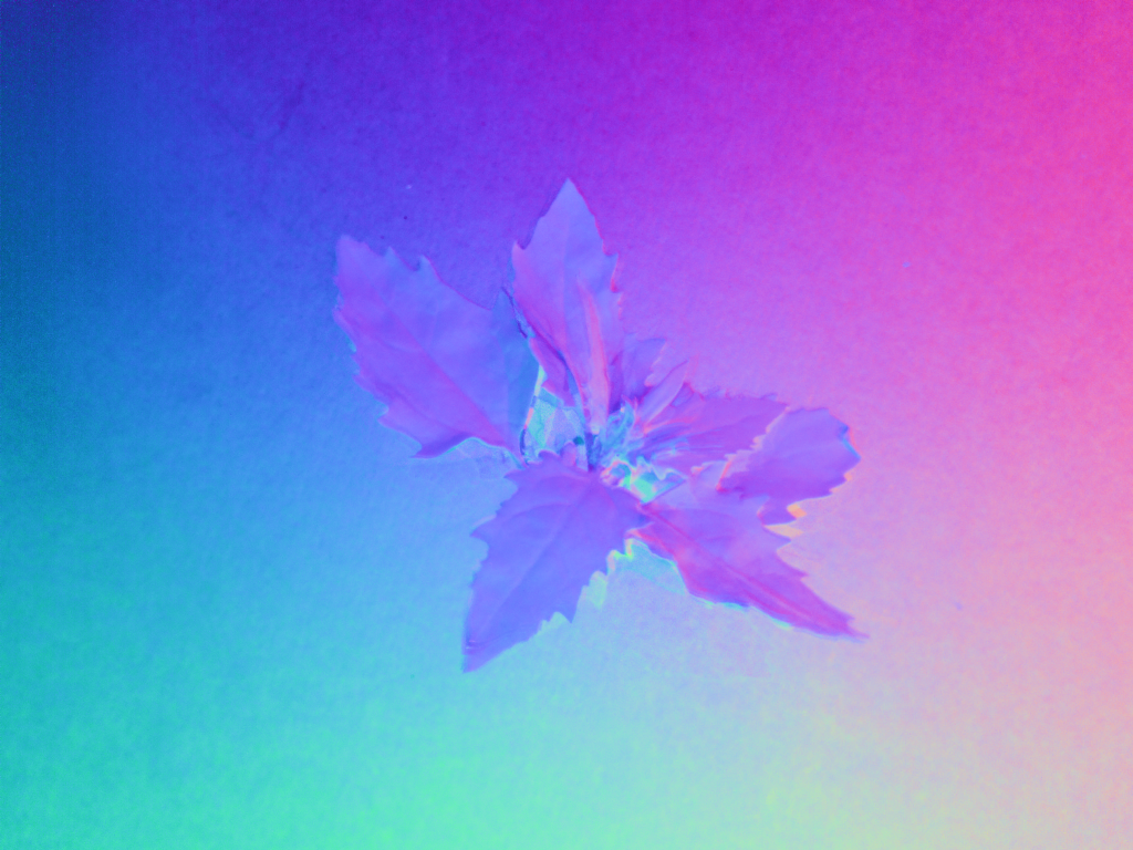
The surface normal map can then be visually represented as a 3-channel image, where 
Improving Robustness
As mentioned above, three images are the minimum required to implement photometric stereo; however, heavily shadowed pixels, or those under specular reflection, offer incorrect information, which is a major source of error. It is therefore common to create an overdetermined system by including additional light-sources.
In future posts, I’ll look at how we might be able to use such an over-determined system and what effect this has on the end-result.
Code
Some basic demo code, with example data is available on my GitHub repo.
References
[1] Woodham, R.J. (1980) Photometric Method For Determining Surface Orientation From Multiple Images. Optical Engineering [online]. 19 (1), pp.191139.
[2] Jiuai Sun, Melvyn Smith, Abdul Farooq and Lyndon Smith. (2010) Counter camouflage through the removal of reflectance.IEEE the 3rd International Conference on Machine Vision. Hong Kong.